
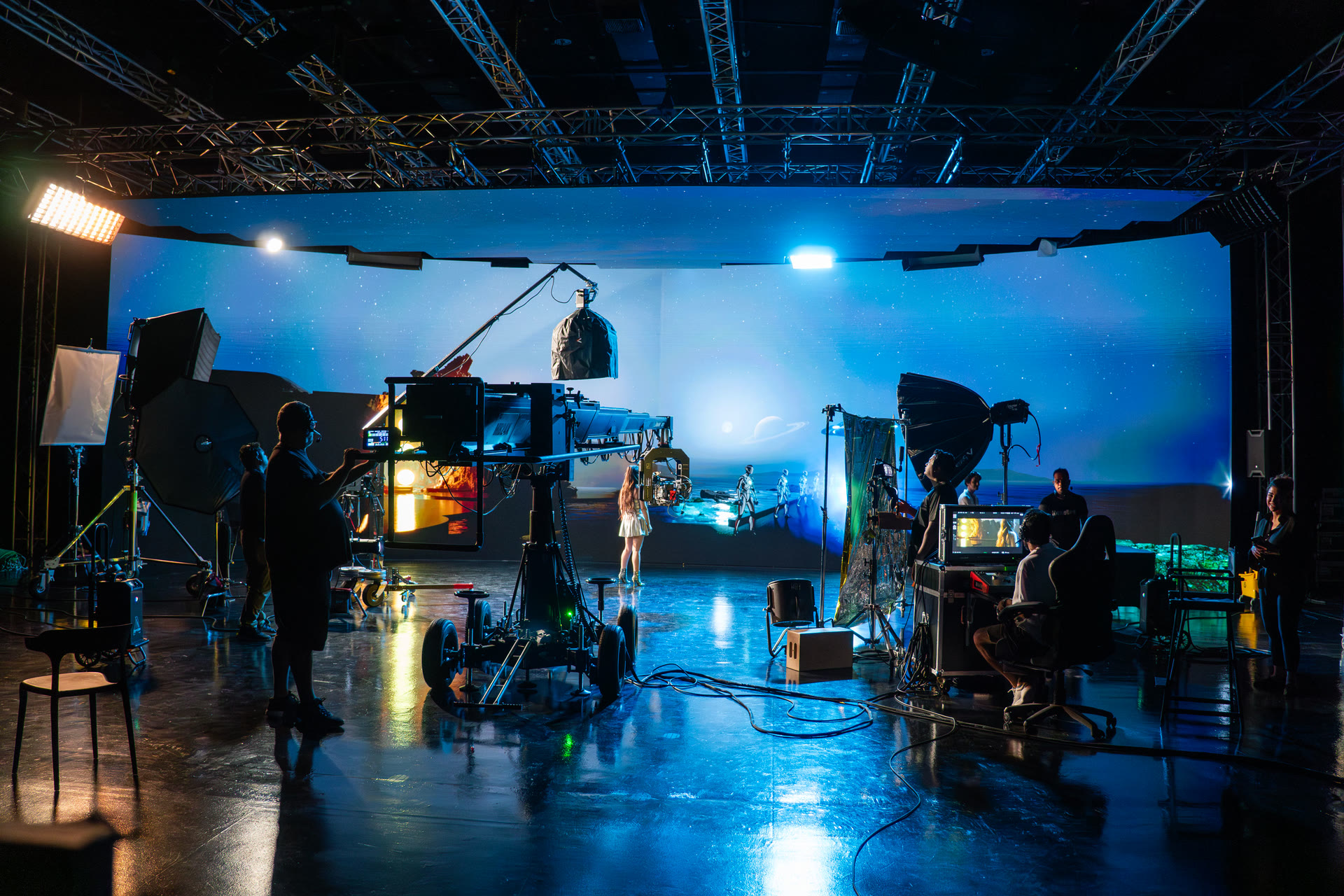
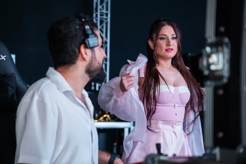
Having worked as a Virtual Production Supervisor and being involved in the development and operation of PixoJam, one of the leading Virtual Production and XR stages in the MENA region, I have learned that building a cinematic LED stage is much more complicated than simply installing a large LED wall and connecting it to Unreal Engine.
A professional Virtual Production LED stage is an ecosystem.
The LED panels, LED processors, render nodes, camera tracking, lens data, Unreal Engine, nDisplay, networking, genlock, color pipeline, physical lighting and camera system all need to work together accurately and reliably.
If even one part of this pipeline is not designed correctly, it can affect the entire production.
This guide covers the most important technical components required to build a cinematic Virtual Production LED stage.
1Studio Size and Physical Stage Design
Before choosing LED panels, render computers or tracking systems, the first requirement is the physical studio itself.
For a large cinematic XR or Virtual Production stage, I recommend having approximately 8 meters or more of ceiling height whenever possible.
The higher ceiling gives you more flexibility to build the LED volume vertically and helps prevent actors, props and camera angles from extending outside the active LED area.
You also need enough floor space for:
- Physical sets
- Practical props
- Camera movement
- Lighting equipment
- Tracking systems
- Art department work
- Crew movement
- Vehicles, when required
The art department needs enough space to integrate physical foreground elements with the virtual environment.
This interaction between the practical set and the virtual environment is one of the most important parts of creating a convincing Virtual Production image.
2Image Based Lighting and Lighting Control
Filming inside an LED volume is very different from working inside a traditional studio.
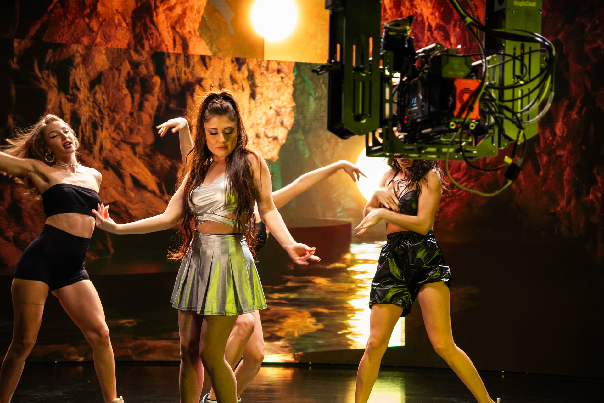
In a normal studio, a cinematographer might use a very large softbox to create broad illumination. Inside an Image Based Lighting environment, however, lighting needs to be much more controlled.
One of the biggest mistakes on an LED stage is allowing physical lights to spill directly onto the LED wall.
When strong light hits the LED panels, it can:
- Reduce black levels
- Lower contrast
- Wash out the displayed environment
- Make the background look flat
- Reduce the illusion of depth between the physical and virtual worlds
This means lighting needs to be carefully shaped, flagged and controlled.
The goal of Image Based Lighting, or IBL, is for a significant percentage of the environmental lighting to come directly from the LED volume itself.
Ideally, the LED environment should contribute roughly 60% to 80% of the scene's environmental lighting, depending on the shot and production.
The LED wall should provide the environmental reflections, ambient color and interactive lighting while traditional cinema fixtures are used to shape the subject where necessary.
If the LED wall is too weak to contribute meaningful light to the scene, the result may start to look like an image displayed behind the actors rather than an environment surrounding them.
At that point, some of the main advantages of shooting on an LED volume compared with a green screen begin to disappear.
3Cinema-Grade LED Panels
The LED panels are one of the most important investments in a Virtual Production stage.
Not every LED panel is suitable for cinematic shooting.
A panel can look excellent to the human eye while producing serious problems when recorded through a cinema camera.
Several characteristics need to be considered.
Pixel Pitch
For cinematic Virtual Production, pixel pitches around 1.5 mm to 2.6 mm are commonly suitable depending on the size of the volume, camera distance, lens choice and production requirements.
The relationship between pixel pitch, camera distance and focus is extremely important.
If the camera gets too close to the LED wall, individual pixels or pixel structures may become visible and create moiré patterns.
Refresh Rate and Scan Rate
Refresh rate is another critical specification.
Some inexpensive LED products may advertise impressive refresh-rate numbers, but the advertised number alone does not guarantee good performance on camera.
The complete LED driving and scan system needs to be tested for the actual camera, shutter, frame rate and production environment.
An unsuitable scan rate or refresh configuration can produce:
- Horizontal scan lines
- Flickering
- Rolling artifacts
- Brightness inconsistencies
- Camera synchronization problems
This is why LED specifications should be evaluated by someone who understands cinema camera behavior, not only live events or broadcast LED installations.
Brightness and Black Levels
High brightness and strong black reproduction are also extremely important.
The LED wall needs enough output to contribute meaningful Image Based Lighting while maintaining convincing blacks and contrast.
Good black levels help create depth in darker environments and improve the transition between the physical foreground and virtual background.
Bit Depth and HDR
Bit depth becomes especially important when the LED wall is being photographed by a high dynamic range cinema camera.
Imagine recording with a cinema camera capable of capturing very high bit depth and more than 15 stops of dynamic range while the LED wall is displaying a limited 8-bit SDR image.
The physical subject and the displayed background are then operating with very different image characteristics.
This can become especially noticeable during grading.
For high-end cinematic Virtual Production, the LED display pipeline should therefore provide sufficient:
- Bit depth
- Dynamic range
- Color accuracy
- Highlight reproduction
- Shadow detail
The goal is to preserve as much flexibility as possible throughout the final color grading process.
4Choosing the LED Processor
Even the best LED panels cannot perform properly without a professional LED processing system.
The LED processor controls a major part of the final image displayed on the volume.
Depending on the system, it can manage:
- Color calibration
- Brightness
- Refresh rate
- Scan settings
- Genlock
- Frame remapping
- Panel configuration
- Signal distribution
Brands commonly used in professional VP environments include LED manufacturers such as:
Professional LED processing platforms include:
The exact combination needs to be selected based on the LED panel model, required resolution, camera system, frame rate, production requirements and overall stage design.
Buying expensive LED panels while using an unsuitable processor can prevent you from accessing the capabilities you paid for.
The processor and LED panels therefore need to be designed as one system.
5Render Nodes and GPU Infrastructure
After the LED system, you need computers capable of generating and delivering the content to the LED processors.
These systems are normally called render nodes.
There are two main workflows to consider.
Playback-Based LED Stage
If the stage is mainly displaying pre-rendered video plates or static media, the rendering requirements can be relatively straightforward.
Real-Time 3D Virtual Production
If you want real-time camera-tracked environments using Unreal Engine, the system becomes considerably more demanding.
Large LED volumes can require extremely high output resolutions, sometimes reaching 16K, 20K or more across the complete installation.
For multi-node rendering, synchronization between GPUs becomes extremely important.
Professional NVIDIA workstation GPUs and synchronization hardware are normally used because multiple render nodes need to remain frame synchronized.
Depending on the required performance and generation of hardware, systems can use professional NVIDIA GPU platforms such as:
- NVIDIA RTX PRO 6000
- NVIDIA RTX 6000 Ada Generation
- NVIDIA RTX A6000
- Other professional RTX or Quadro-class GPUs that support the required synchronization workflow
A high-end consumer GPU can provide exceptional rendering performance, but a professional VP installation also needs to consider multi-GPU and multi-node synchronization.
If the architecture requires multiple synchronized render nodes, GPU synchronization capabilities become part of the system design.
Other Render Node Components
The GPU is only one component.
A reliable render node also needs:
- Powerful and stable CPU
- Large amount of RAM
- Very fast local NVMe storage
- Reliable motherboard
- Professional network interface
- Correct power delivery
- Effective cooling
- Stable drivers and firmware
The complete machine needs to be engineered as a system.
During a commercial shoot, a small instability can stop the entire production.
For that reason, stability is often more important than achieving the highest possible benchmark score.
6Local NVMe Storage vs Network Storage
For the active Unreal Engine project, I prefer using fast local NVMe storage on the workstation or render node rather than directly running the complete real-time project from shared NAS storage.
Even a very fast 20 GbE or 40 GbE NAS can be excellent for:
- Source control
- Project backups
- Editing
- Large media transfers
- Centralized storage
But a real-time Virtual Production Unreal project benefits from fast and predictable local asset access.
Shared storage should instead act as the central project repository and source-control location.
Each Unreal workstation and render node can then synchronize its local project with the main repository.
7Unreal Engine for Real-Time Virtual Production
For real-time 3D Virtual Production, Unreal Engine is one of the most established solutions available.
However, preparing an Unreal Engine environment for an LED volume is not the same as optimizing a game.
A Virtual Production environment needs to be designed around the requirements of:
- Real-time cinematic rendering
- LED resolution
- Camera frustum rendering
- Multiple render nodes
- Stable frame rate
- Synchronization
- Cinematic lighting
- Live production reliability
The VP Supervisor needs to ensure that systems such as Nanite and Lumen are configured correctly for the specific stage and environment.
Animations, media plates and time-dependent content also need to operate at the correct frame rate.
A small timing problem inside the Unreal environment can become visible as jitter, lag or frame inconsistency on the LED wall.
On a production day, the environment cannot simply look good.
It needs to look good while remaining stable in real time.
8Camera Tracking
Camera tracking is one of the technologies that makes real-time Virtual Production so powerful.
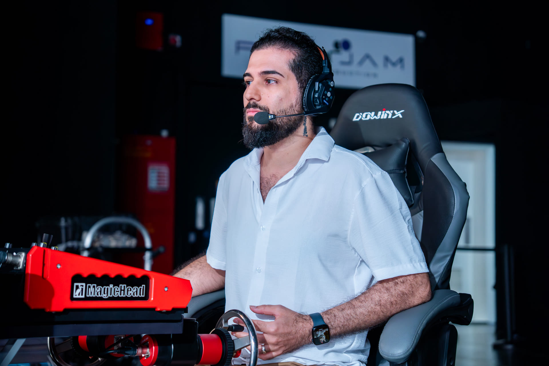
The tracking system continuously measures the physical camera's position and orientation and sends that information to the Unreal Engine render system with extremely low latency.
Unreal then updates the virtual camera.
This creates correct perspective and parallax between:
- Physical foreground objects
- Actors
- Practical set pieces
- The virtual environment displayed on the LED volume
As the real camera moves, the Unreal environment responds to that movement.
Without accurate tracking, the virtual background will not move correctly relative to the physical set.
The viewer immediately begins to see sliding, incorrect perspective and a visual separation between the real and virtual worlds.
Professional tracking systems can include platforms from:
Different tracking technologies use different methods.
Some systems use physical markers or references installed around the studio, while others use optical camera-based tracking systems.
Both approaches can provide excellent results when properly installed, mapped and calibrated.
9Lens Tracking and Lens Calibration
Tracking the physical camera position alone is not enough.
The virtual camera also needs to understand what is happening with the real lens.
Important lens information can include:
- Focal length
- Focus distance
- Aperture
- Lens distortion
- Field of view
Many professional tracking systems can send lens data to the render nodes, but transmitting the numerical lens values is only part of the process.
Every lens behaves differently.
Two lenses set to the same focal length and aperture can still produce different:
- Distortion
- Field of view
- Focus behavior
- Bokeh
- Optical characteristics
For a highly accurate setup, lens profiles therefore need to be prepared and carefully organized.
The profile may also depend on the camera body and recording format.
For example, using a Cooke S8 35 mm on a Sony Venice 2 and using the same lens on a RED V-Raptor may require separate calibration profiles.
The same concept can apply when changing sensor recording formats.
For example, a lens used with one camera in an 8K sensor mode may require a different calibration compared with another cropped recording format.
On a large production, the number of lens calibration profiles can become substantial.
A well-organized calibration database is therefore extremely important.
10Lens Distortion Data for Set Extension and Post-Production
If you are planning to extend the virtual set or composite additional CG elements into the original camera footage later, lens distortion information becomes even more important.
The rendered image needs to match the optical characteristics of the original camera footage.
Otherwise, you can see:
- Sliding
- Edge mismatch
- Incorrect perspective
- Distortion inconsistencies
For this reason, distortion data should be captured and organized together with the other camera and lens calibration information.
All of this information eventually becomes part of the data pipeline feeding the primary Unreal render system, commonly through systems such as Live Link.
11Genlock and Frame Synchronization
Synchronization is one of the most critical parts of a professional Virtual Production stage.
It is not enough to synchronize the render nodes with each other.
The complete system needs to operate on the same timing reference.
This can include:
- Cinema camera
- Render nodes
- LED processors
- LED wall
- Video infrastructure
Even a very small timing mismatch can create visible problems.
This is where genlock and synchronization generators become essential.
Professional synchronization solutions are available from companies such as:
Without proper synchronization you can experience:
- Image tearing
- Horizontal lines
- Rolling artifacts
- Frame mismatch
- Unstable LED capture
A Virtual Production stage is essentially a chain of synchronized systems.
If one part of that chain is running out of time with the others, the problem can become visible directly inside the recorded camera image.
12Timecode
Timecode may not directly generate the final LED image, but it becomes extremely useful in more complex productions.
It is particularly valuable when working with:
- Multiple cameras
- Audio recording
- Motion capture
- External recorders
- Camera tracking data
- Take Recorder
- Post-production
For example, recording camera tracking information together with accurate timecode can save significant time if additional virtual elements need to be added later.
Instead of re-tracking the camera from the recorded footage, the original tracking data can potentially be synchronized with the camera source.
This becomes even more useful in green screen and hybrid Virtual Production workflows.
Common approaches include LTC and embedded timecode.
13Choosing the Camera System
The cinema camera is another component that needs to be chosen carefully for LED volume shooting.
Important capabilities can include:
- Genlock support
- Sensor scan behavior
- Shutter control
- Color science
- Dynamic range
- Frame rate options
- Sensor timing adjustments
Depending on the camera and LED combination, sensor timing or shutter-related adjustments may sometimes help reduce certain LED artifacts.
Professional cameras frequently used for this type of work include:
- ARRI Alexa 35
- ARRI Alexa Mini LF
- Sony Venice
- Sony Venice 2
- RED V-Raptor
- RED Komodo-X
- Blackmagic URSA Cine for more budget-conscious productions
However, using a high-end camera does not automatically solve LED problems.
An Alexa 35 shooting a poorly configured LED wall can still record artifacts.
Likewise, an excellent LED wall combined with incorrect synchronization can still produce problems.
The camera, LED panels, processor, synchronization, tracking and render system all need to operate together.
14nDisplay, ICVFX and Switchboard
When working with Unreal Engine, nDisplay becomes one of the central systems controlling how content is rendered across the LED volume.
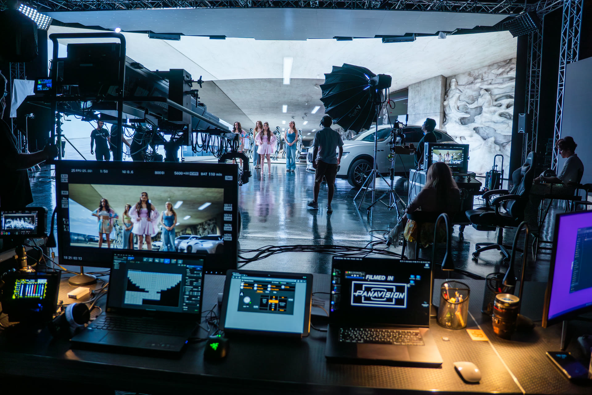
The nDisplay configuration defines how the render cluster is organized.
Depending on the stage, you need to configure:
- Render nodes
- Primary node
- Cluster configuration
- LED display geometry
- Viewports
- GPU allocation
- ICVFX camera
- Frustum rendering
- Rendering quality
- Output resolution
Switchboard is then used to help manage and launch the Unreal systems across the render cluster.
The VP team needs to understand how much rendering quality can be pushed while still keeping enough system resources available to maintain stable real-time performance.
The goal is not simply maximum quality.
The goal is the highest possible quality that remains completely reliable throughout production.
15ICVFX Camera
The ICVFX camera defines the area of the LED wall that represents the camera's correct perspective into the virtual environment.
This inner frustum follows the tracked cinema camera.
Outside this region, the LED wall can display content primarily designed for environmental lighting and reflections.
Correctly configuring the ICVFX system therefore affects both:
- The image recorded directly by the camera
- The environmental illumination surrounding the physical set
Resolution, overscan, rendering quality and frustum behavior all need to be balanced against the available GPU performance.
16Multi-User Unreal Engine Workflow
During production, Unreal Engine is not a system that should simply be configured before the shoot and then left untouched.
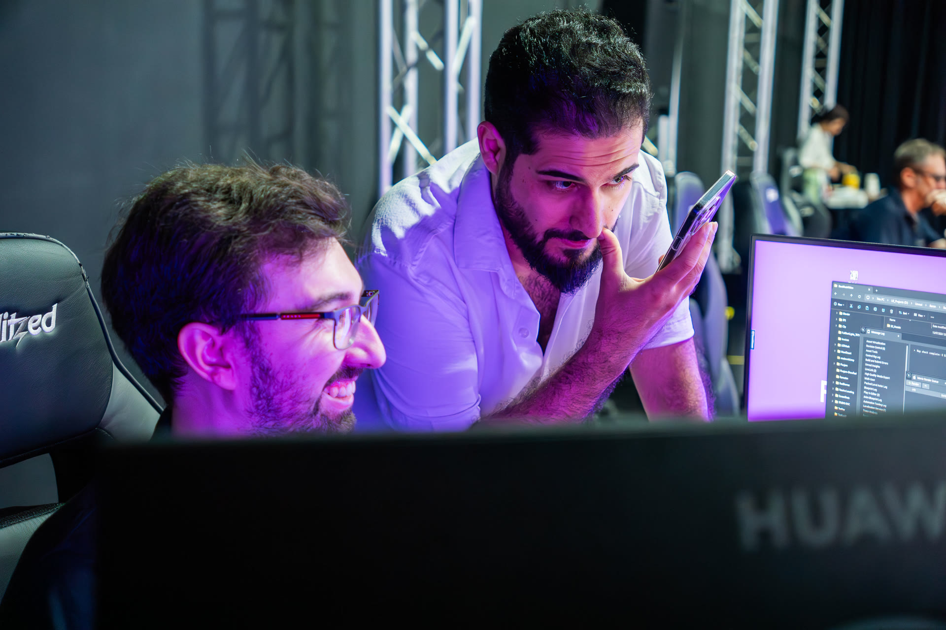
The environment often needs to be adjusted live while looking through the actual cinema camera.
This is where Unreal's Multi-User workflow becomes extremely useful.
Different operators and artists can work with the virtual environment while the primary render system continues to drive the LED volume.
During the shoot, adjustments may include:
- Virtual light intensity
- Light direction
- Color temperature
- Environment brightness
- Textures
- 3D assets
- Reflections
- Atmosphere
- Background placement
- Scene composition
These decisions need to be made while looking at what the cinema camera is actually recording.
17Collaboration Between the DOP and VP Supervisor
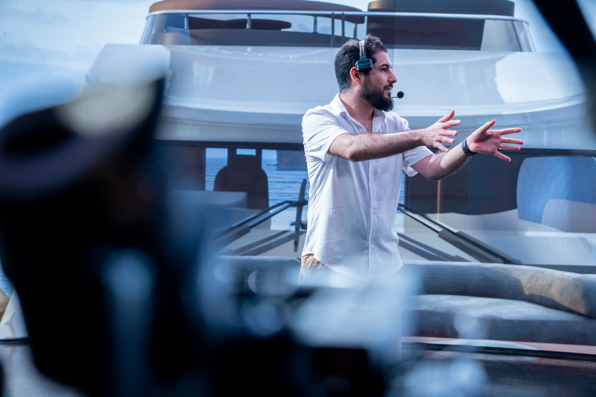
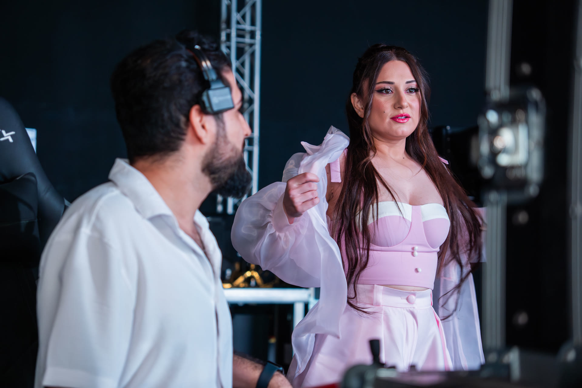
Virtual Production works best when the cinematographer and VP Supervisor work as one team.
It should not be:
"The Unreal team finishes the virtual lighting, and then the DOP lights the physical set."
Both sides affect each other.
The DOP may change the physical key light.
The VP Supervisor may then adjust the virtual environment to maintain continuity.
Or the VP Supervisor may change the environmental lighting, requiring an adjustment to the physical lighting.
This process continues until the real and virtual worlds visually become one environment.
For this reason, a VP Supervisor working on cinematic Virtual Production needs more than Unreal Engine knowledge.
Understanding cinematography, lighting, lenses, exposure, color and composition is extremely valuable.
The VP Supervisor should be working close to the director and DOP throughout the production.
18Live Color Adjustment Inside Unreal Engine
Beyond adjusting individual lights, materials and assets, it is also useful to have overall live control of the virtual environment.
Remote interfaces such as tablets can be connected to Unreal Engine to give the VP team faster access to important parameters.
This allows final adjustments to things such as:
- Environment exposure
- Color balance
- Light intensity
- Saturation
- Contrast
- Atmosphere
These adjustments help match the virtual environment to the physical lighting and practical set while everyone is looking at the final result through the cinema camera.
19Network Infrastructure
A professional Virtual Production stage depends heavily on its network.
Tracking data, Unreal communication, render-node management, editors and control systems all need to communicate with extremely low latency.
I recommend a minimum 10 GbE network infrastructure for the main VP systems, with faster networks used where the stage architecture requires them.
It is also useful to separate different parts of the system.
For example:
- Render network
- Unreal editor network
- Tracking network
- Storage network
- General production network
Separating traffic can improve reliability and make troubleshooting much easier.
For critical real-time Virtual Production communication, wired networking should always be preferred over Wi-Fi.
Even when Wi-Fi offers high theoretical speed, bandwidth stability and latency are different concerns.
Virtual Production depends on predictable communication.
21Color Pipeline
A professional LED stage needs a clearly designed color-management pipeline.

You need to understand:
- LED native color space
- Camera color space
- Unreal Engine working color space
- OCIO transforms
- Monitoring transform
- Final delivery color space
ACES is commonly used in professional productions because it provides a structured way to manage different cameras, display systems and post-production environments within the same pipeline.
Unreal Engine can use OCIO to transform the rendered environment appropriately before it is displayed on the LED wall.
The important point is that color management should be planned across the complete image chain rather than treated as an isolated Unreal Engine setting.
22LED Wall Calibration
Never assume a newly installed LED wall is automatically ready for cinematic shooting.
The volume needs to be properly calibrated.
This can include:
- White point
- RGB balance
- Brightness uniformity
- Gamma
- Color gamut
- Panel matching
Professional calibration tools can include:
- Spectroradiometers
- Colorimeters
- Calibration software
Depending on the production and camera system, additional calibration and matching may be required.
The LED wall, camera, Unreal output and monitoring environment should always be considered as parts of the same color pipeline.
23Physical Cinema Lighting
An LED wall does not completely replace traditional film lighting.
The LED volume is extremely useful for generating:
- Reflections
- Interactive lighting
- Environmental color
- Ambient illumination
- Background light
But physical cinema fixtures are still normally required to shape the subject.
Common fixtures used around Virtual Production stages can include systems from manufacturers such as:
The exact fixture is less important than how it is controlled.
The lighting team needs to prevent unnecessary spill from hitting the LED wall while keeping the physical illumination consistent with the virtual environment.
Color temperature also needs careful attention.
The LED environment, physical fixtures and camera white balance should work together to create one believable lighting environment.
24Matching the Physical and Virtual Worlds
At the end of the process, numbers and calibration can only take you so far.
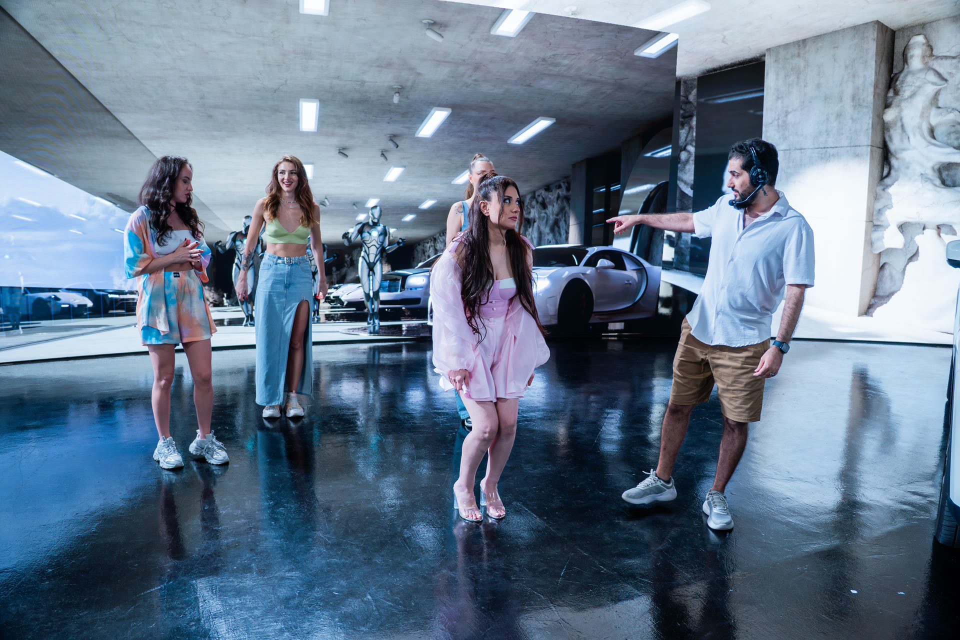
The real challenge is making the audience believe that the physical foreground and virtual world are the same space.
You can mathematically calibrate:
- Camera position
- Lens
- Color
- White point
- Exposure
- Tracking
- Synchronization
But after the technical calibration is complete, the scene still needs to be judged visually.
This is where cinematic experience becomes important.
You need to look through the actual camera and evaluate whether the transition between reality and the virtual environment feels natural.
The final matching process requires both technical accuracy and a strong visual eye.
25Dedicated Camera Monitoring
The VP Supervisor and Unreal operators should have access to the actual cinema camera feed.
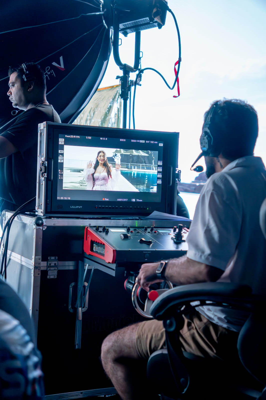
Looking only at the Unreal Editor viewport is not enough.
The final image is what the physical camera records after combining:
- LED wall
- Virtual environment
- Physical lighting
- Practical set
- Actors
- Camera exposure
- Lens characteristics
- Reflections
Every important adjustment should therefore be evaluated through a properly monitored camera feed.
This helps the Unreal team understand how their changes affect the actual recorded image rather than only the rendered scene.
26DMX, Remote Control and Advanced Integration
A professional Virtual Production stage can also integrate systems such as:
- DMX
- Unreal Remote Control
- Lighting consoles
- Real-time scene controls
These tools can make production considerably faster.
For example, virtual lighting and physical lighting can be controlled together so a change in the Unreal environment can be matched immediately by the lighting department.
This level of integration becomes particularly useful for:
- Day-to-night transitions
- Moving light sources
- Interactive environments
- Vehicle sequences
- Dynamic backgrounds
The goal is to reduce the distance between the physical set and the virtual world until both operate like parts of the same lighting and production system.
Building a Virtual Production Stage Is About the Complete System
A cinematic Virtual Production LED stage cannot be judged by the size of its LED wall alone.
A serious VP stage requires the correct combination of:
Every component affects the others.
You can have the best cinema camera in the world, but if the LED scan system is wrong, you can still record artifacts.
You can have an incredible LED wall, but if the camera tracking is inaccurate, the perspective will not feel natural.
You can have the most powerful Unreal Engine render nodes available, but without proper synchronization, networking and optimization, the production can still fail.
The real objective of Virtual Production is not simply to place an actor in front of a digital background.
It is to combine the camera, LED volume, Unreal Engine environment, physical set, lighting and color pipeline so accurately that the audience cannot identify where the physical world ends and the virtual world begins.
That is what turns an LED installation into a cinematic Virtual Production stage.
?Frequently Asked Questions
How high should the ceiling be for an LED volume stage?
For a large cinematic XR or virtual production stage, around 8 meters or more of ceiling height is recommended where possible. It lets you build the LED volume vertically and keeps actors, props and camera angles inside the active LED area.
What pixel pitch is best for a cinematic LED volume?
Pixel pitches around 1.5 mm to 2.6 mm are commonly suitable, depending on the size of the volume, camera distance, lens choice and production requirements. Getting too close to the wall can reveal pixel structure and create moiré.
How much of the lighting should come from the LED wall?
Ideally the LED environment contributes roughly 60% to 80% of the scene's environmental lighting, with traditional cinema fixtures shaping the subject where needed.
Why is genlock so important on an LED stage?
The cinema camera, render nodes, LED processors, LED wall and video infrastructure all need the same timing reference. Without proper synchronization you can record tearing, horizontal lines, rolling artifacts and frame mismatch.
What network does a virtual production stage need?
A minimum 10 GbE wired network is recommended for the main VP systems, ideally separated into render, Unreal editor, tracking, storage and general production networks.
Can you design and build an LED volume stage outside the UAE?
Yes. Hamed Tayebi designs and builds cinematic LED volume stages on location anywhere in the world, and also fixes workflows and pipelines on existing stages.
© 2026 Hamed Tayebi. All rights reserved. This guide and its diagrams are original work and may not be copied, republished or reproduced without written permission.